Washington, NC Real Estate - A cool site with real estate information in Washington, Bath, and Belhaven, North Carolina.
Greenville, NC Real Estate - Another real estate site with information for Greenville and Winterville, NC.
Morehead City, NC Real Estate - Another real estate site with information for Atlantic Beach and Emerald Isle, NC.
Jacksonville, NC Real Estate - A real estate site with information for Jacksonville, NC and Richlands, NC and homes for sale.
|
Occupancy Detection & People Counting
 One of the key elements of every home automation system is occupancy detection. Knowing whether or not someone is in a room, or even in the house at all is vital. For years I, like everyone else, used motion detectors around the house to identify when someone enters a room. Then every time it senses motion in the room it would reset a timer. When the timer expires due to no motion in the room for X number of minutes the system would assume the room is unoccupied. One of the key elements of every home automation system is occupancy detection. Knowing whether or not someone is in a room, or even in the house at all is vital. For years I, like everyone else, used motion detectors around the house to identify when someone enters a room. Then every time it senses motion in the room it would reset a timer. When the timer expires due to no motion in the room for X number of minutes the system would assume the room is unoccupied.
Motion detectors for occupancy detection have many disadvantages. For starters, when someone is sitting still for a while no motion is ever reported and you end up with the lights turning off on you in the room. This resulted in having to wave your arms in the air to make the motion detector “see you” again. The next big problem is the delay. My motion detectors take about 2 to 3 seconds to recognize motion in the room. This means that I would end up walking several feet into a dark room before the lights turn on. Using a true “Occupancy Detector” instead of a motion detector cures this problem, but they are so sensitive that they often detect my cat walking on the floor.
Because of these drawbacks I began to look for a different method to detect occupancy. I considered several options including facial recognition (way too costly and bulky), sonar (not accurate enough), and floor sensors (not accurate enough either).
I eventually came up with a concept idea. What if I could place two infrared beams across each of the door frames in my house so that I could count the number of people that enter and exit each room? The idea sounded crazy, but the more I got to thinking about it the more it made sense. I began to look around on the internet for a pre-made solution and the only thing I could come up with that was even close was a device that is used to count the number of customers that enter and exit a retail store. This thing was not only expensive, but very bulky. Not to mention I have no idea how to get the output to my main controller for counting.
Several weeks went by looking for other solutions and I finally decided I was going to have to make the device myself. Now, I am not an electrical engineer. Or a programmer by trade. Everything I know about electronics, home automation, circuits, design, and programming all come from me searching the internet and learning about it myself. You have been warned.
The Idea – the 'Door Node'
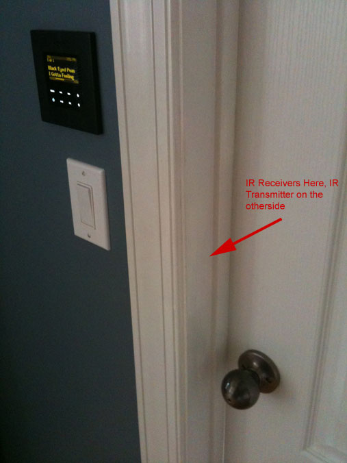 My idea involves two infrared LEDs on one side of the door frame that shoot two invisible beams of light across the doorway to the other side at 38kHz. On the side opposite of the infrared LEDs there are two infrared receivers that detect when the light is present or not. The wires from both sides of the door frame will connect to the door node that houses the bulk of the electrical components. I want this setup to be as aesthetically pleasing as possible, so since my house has a crawlspace I planned to take the wires on both sides of the door frame straight down through the floor where they will connect to the main device completely hidden out of sight. With the main device mounted in the crawlspace beneath the floor, I will connect it to my RS485 network so that it can communicate back to my main controller. Running power to each of the door nodes would be a tedious task, so I opted to use the power from my RS485 network that I already distribute to other nodes. In the case that I have so many of the door nodes that they draw too much power, I dedicate a new power adapter for every 4 or so door nodes – all running from my wiring closet. My idea involves two infrared LEDs on one side of the door frame that shoot two invisible beams of light across the doorway to the other side at 38kHz. On the side opposite of the infrared LEDs there are two infrared receivers that detect when the light is present or not. The wires from both sides of the door frame will connect to the door node that houses the bulk of the electrical components. I want this setup to be as aesthetically pleasing as possible, so since my house has a crawlspace I planned to take the wires on both sides of the door frame straight down through the floor where they will connect to the main device completely hidden out of sight. With the main device mounted in the crawlspace beneath the floor, I will connect it to my RS485 network so that it can communicate back to my main controller. Running power to each of the door nodes would be a tedious task, so I opted to use the power from my RS485 network that I already distribute to other nodes. In the case that I have so many of the door nodes that they draw too much power, I dedicate a new power adapter for every 4 or so door nodes – all running from my wiring closet.
The logic for determining when someone crosses a door frame, and what direction they went will be handled by a PIC16 series micro controller. By sensing which of the two beams “breaks” first as someone crosses the door frame, I can detect the direction they travel in. This sounds simple, but in reality a bunch of error checking and problem scenarios have to be implemented. Once a successful pass is determined by the door node, it will communicate back to the main controller the direction that the person traveled in. The main controller then uses logic to keep track of the number of people in each room based on how many enter the house and from what rooms they travel to from there.
 Infrared LED
|
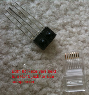 Infrared Receiver
|
Installing the LEDs and Sensors
This was a bit of trial and error at first, but I eventually got the hang of it. I don't have any experience when it comes to construction or wood work, so I was a bit hesitant to attempt this at first. Eventually I gathered up enough courage to wake up one morning and (very carefully) remove the molding from around my office door frame. Most of the doors in my house are three foot wide. I do have some french doors that are considerably wider as well.
 Left side of door frame with molding removed
|
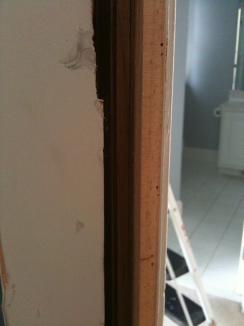
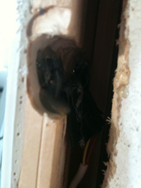
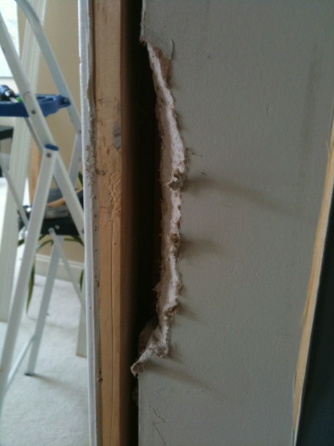 Right side of door frame with molding removed. I had to cut away some of the dry wall that was hanging over the hole.
|
As you can see from the picture there is a gap between the actual door frame and the studs holding up the wall. Shims are used between this gap to nail the door frame to the stud so that it can be perfectly leveled and squared. This gap is what allows me to run my wire for the sensors without being seen. My door frames in my house are tapered (not sure if this is a standard) so that the part closest to the molding is thicker and gradually gets thinner as it goes in. This means that the thickness was not the same, and thus my two IR LEDs or the two IR sensors on the other side would not be even. So I took out my handy dremel tool and routed out the extra thickness so that the LEDs or sensors would have an even surface to attach to. Then, using a template I made with Google SketchUp, I drilled two small holes on each side of the door frame exactly 43.5” from the floor so that I had four total holes, two for the IR LEDs on one side, and two for the IR sensors on the other. The drill bit I used for the IR LEDs was 13/64”, and 11/64” for the receivers.
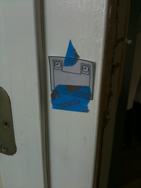 Right door frame with template placed before holes are drilled
|
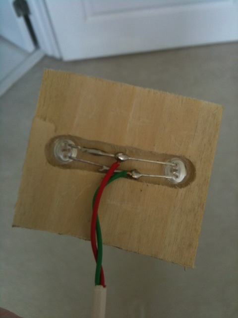 Scrap peice of wood used for molding the two IR LEDs so they can be soldered
|
I used my molding trim color paint (white) to paint the inside of the holes I drilled so that they would not be wood-colored and thus less noticeable. While the paint in the holes dried, I drilled a small hole in the floor in the gap between the door frame and the wall stud that the wire for the IR LEDs could run through. I did the same on the other side for the receivers as well.
 Hole to crawlspace below the floor between the gap, hidden behind the molding.
|
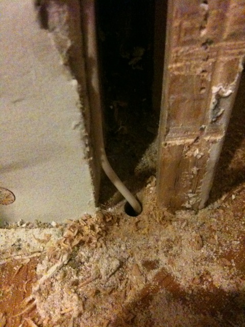
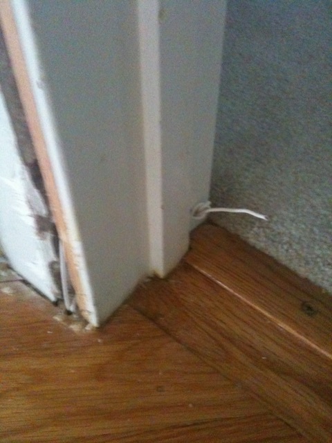 A different door showing the hole to the crawlspace below. Note: The knotted wire is for a magnetic door switch (see below).
|
I used a mixture of hot glue and super glue to mount the sensors inside the door frame. I probably went overboard with the hot glue, but I wanted to make sure those things were not going anywhere once I put the molding back on.
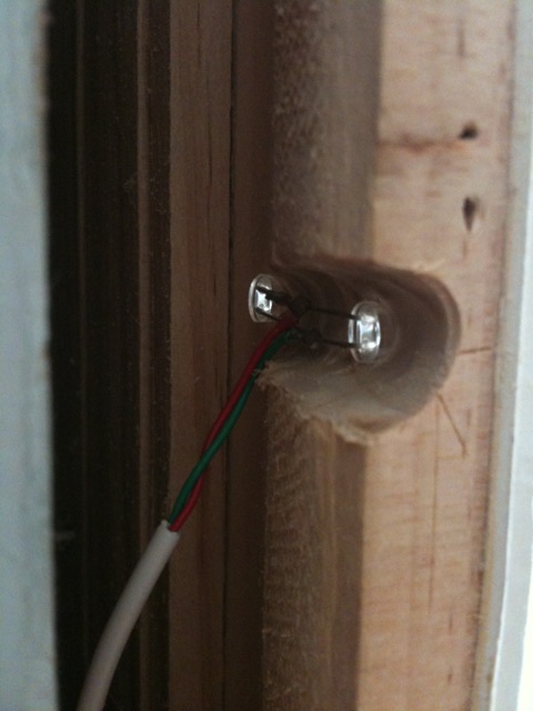 Testing the placement of the IR LEDs before insulating with electrical tape and gluing
|
 Testing the placement of the IR LEDs. Notice the glow from them seen only by the camera.
|
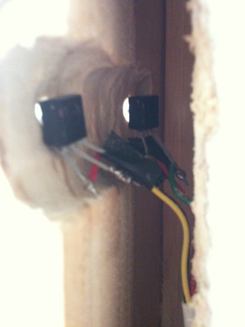 Testing the placement of the IR sensors before insulating with electrical tape and gluing
|
 IR sensors insulated with electrical tape and glued
|
I tested the sensors thoroughly using a breadboard prototype I had created before I put the molding back. My main concern was making sure they all aligned perfectly. After that was confirmed, I pushed the wires in the gap and nailed the molding back on. After some painters caulk to hide the seams and a fresh coat of paint, you can't even tell the molding was ever removed. All that is visible are two small holes on each side of the door frame.
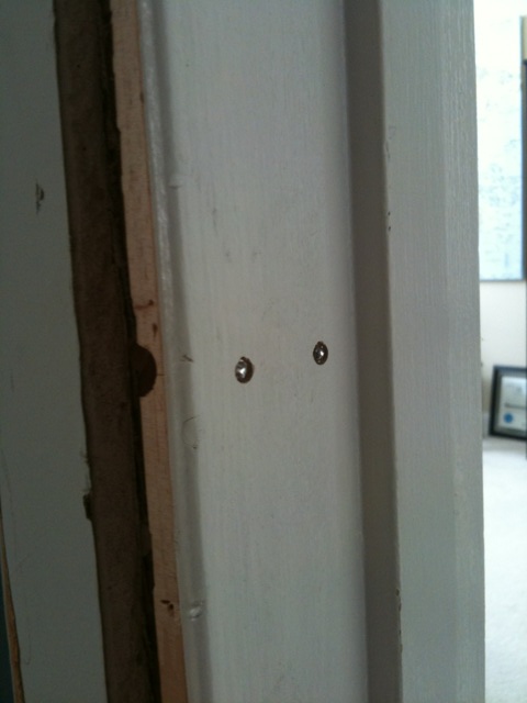
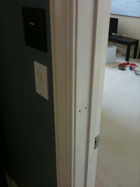 Left side of completed door
|
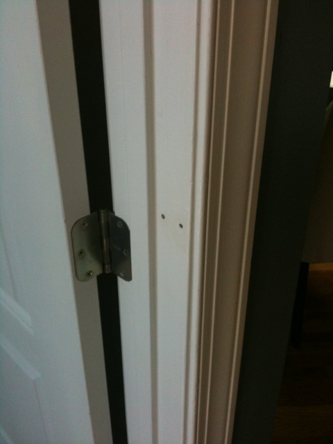 Right side of completed door
 |
Building the First 'Door Node'
I had already been playing with a prototype I made on a breadboard, but I had not gone any further to make it a usable device. I decided on the following physical features for each of the door nodes I wanted to build:
-
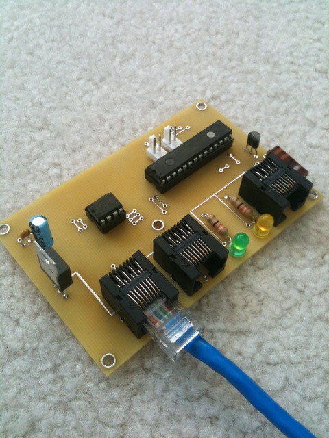
2x RJ45 Jacks for Network/Power - I like things to be modular, so I opted to use standard RJ45 (ethernet) jacks for connecting to my RS485 network. I didn't want to have to run a new wire run for each of the door nodes all the way back down to my crawlspace, so I added an additional RJ45 jack that could be used to connect to the next door node directly. This allowed me to “daisy chain” the nodes together easily in the crawlspace. The only time I would need to run a new wire run all the way back to the wiring closet was if I needed another power adapter because they were drawing too much power.
-
1x RJ45 Jack for Sensor Connections - I also use a RJ45 jack to connect the sensor wires together down below in the crawl space. This makes it easy to unplug it if I need to take it back to my desk to work on it. Then I just plug it back in when I put it back in the crawlspace. I opted to use only one jack for BOTH the LEDs and sensors. Four wires are used for the sensors and two wires are used for the LEDs, for a total of 6 wires. I could have split them up into two jacks, but it was just a waste since one would work just fine.
-
2x Contact Closure Inputs – I have magnetic door sensors installed on all my exterior doors for my security system, but hardly any on my interior doors. It was just too much work to run these in the past. Since I was going to pull the molding off the door frames anyway, I figured I might as well add door sensors to all the doors. Because of this I added the ability for each door node to have two contact closure inputs that could be used for anything – magnetic door contacts, deadbolt sensors, etc.
-
2x Status LEDs – These two LEDs are used to see the status of the IR beams. One LED for each beam. This way you can tell if they are aligned correctly just by looking at the board.
-
1x Voltage Regulator – Because I am distributing the power to the door nodes over my network cable, I use an on-board voltage regulator on each of them to bring the power down to a steady 5 volts.
I created my first prototype on perf board and it took me quite a few hours. Needless to say I was pretty happy when I finally got the chance to plug it in and it worked. I don't mind perf boarding when I need to make just one of an item, but when it comes to needing more than that I would rather design a printed circuit board and pay to have them printed. Soldering the components to the PCB board only took me about 20 minutes for each one. You can see the picture below of a completed door node on the new PCB board.
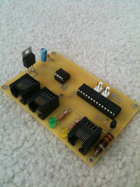 Completed PCB - Front
|
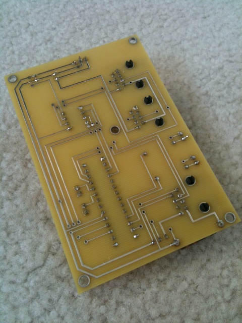 Completed PCB - Back
 |
Logic Behind the 'Door Node' – Programming the Micro Controller
At first the concept of detecting when someone passes through through the door frame and determining which direction they went in based on which of the two infrared beams was “broken” first sounded pretty simple. I found out fast that it was much more complicated than that. Nonetheless I figured it out and ended up with the following features:
-
What about when someone swings their arms as they walk in? Since the sensors are mounted exactly 43.5 inches above the floor, it eliminates most of the problems that would occur from this. Now, if you have something in your arms that sticks out, most likely it will block both beams the entire time that you and the thing you carry cross through the doorway. In order to prevent the counter from seeing some object that is ob-longed shaped and their torso as another, I made it so that the both beams have to be broken for a minimum amount of time (in milliseconds) or the count will be canceled. The thickness of the average torso from the side allows me to guarantee that both beams will be broken for this minimum amount of time given that they walk at a normal pace. Now, if someone were to run full-speed through the doorway, it won't count them. But sprinting all the way down to barely moving will be counted correctly. The minimum time needed for both sensors to be covered is entirely configurable via network commands and is saved in the PIC16's flash memory.
-
What about when someone enters the doorway and stands there? I added some logic that would check which beam was returned to normal first so that I could detect, even after someone stood in the doorway for a long time, which direction they ultimately decided to go in. If someone walks in the doorway and stands there, then backs up, no update is ever transmitted. However, if the same thing happens and someone does decide to continue through the doorway, then the update is transmitted. Again, it's all based off of what beam is restored first.
-
What if someone walks in right behind me? Unless you are literally holding on to each other with no space between your torsos, the beams will be restored as soon as the first person passes. I have a very small time threshold that must be met for both beams to be clear before the next person can walk in in order to prevent baggy clothing from setting off the sensor. The amount of time between people is also a setting you can set over the network and saved in flash memory.
-
What about walking side-by-side? I don't have this problem as my doors are only 3ft wide for the most part and I don't know of a time where I would walk side-by-side with someone through the doorway. The french doors are a different story. For these, it just won't be as accurate if you have multiple people who walk in and out side by side. For the times that I do have an inaccurate update, the logic in the main controller should be able to tell if there was a slip up based off of what rooms are connected and how many people walk into each of these rooms.
-
What is someone waves their hand over the sensor to run up the count? This could happen, but they would have to do it slow enough for both beams to be broken for the minimum amount of time I specified. If someone waves their hand over it the counter just ignores it.
-
What about TV remotes? TV remotes do operate on the same frequency of IR that I am using (38kHz), however, because of the minimum time required for both beams to be broken, they don't cause a problem. They transmit way to quick (even holding down a button) for the signal to meet the time threshold.
-
What about sunlight? So far I haven't had a problem. My sensors on my exterior doors are burrowed down at least half an inch from the edge (my exterior door frames are much thicker than my interior ones), so sunlight can't get to it directly.
-
What about node addressing? Each door node is assigned a letter on my network. I can change this using network commands and it is saved in flash memory. By default when it is powered up for the first time since programming, it assigns itself the temporary address of 'X'.
Main Controller Logic
This is the exciting part. Now that all of my door frames have door nodes installed on them, I can not only tell when someone enters a room, but I can count how many enter as well. Using this information you can do some pretty amazing things. For example:
-
Lighting – Lights come on in a room immediately upon entering. If you are the last person in the room the lights immediately go off when you leave. The main controller knows how many people are in the room, so if two people walk in and one leaves, the lights remain on until the last person leaves. The same goes for ceiling fans based on temperature in the rooms and HVAC modes currently set.
-
Whole-House Occupancy Counting (auto shutdown) – Because I have sensors on all my exterior doors, I can also keep track of how many people are in my house. Using this information I can auto-arm the security system and turn off all the lights if the last person leaves the house. This will only happen if the following things occur: a) no one is in the house, b) the garage door has closed recently in the past two minutes, c) a vehicle backs OUT of the driveway (I have a directional vehicle detection system that detects the direction of a vehicle entering/leaving) recently in the past two minutes, and d) the security system is ready for arming. The exterior lights on my house will dim down for 30 seconds to let me know while I'm backing out of the driveway that the house is shutting down.
-
Whole-House Occupancy Counting (sleeping) – Because I know how many people are in the house, if all people are on beds (see the Bed Occupancy Detector Node) – including guests if there are any, I can shutdown the house into sleeping mode automatically.
-
Music Following – This is something that I am currently testing. This allows music to follow me or whoever turns music on in a zone around the house on the Nuvo Grand Concerto automatically.
-
Blind/Shade Control – This is something else that I am currently testing. I'll put more details up on this later.
Reliability and Error Detection
Honestly, the sensors are more reliable than I thought they would be when I first started this project. I have sensors on all my interior and exterior doors at the moment. The only problem I ever encounter tends to occur when you are holding a strange shaped or translucent object in your hand as you walk through the beams. Occasionally the door node can end up not reporting the pass because ultimately the way the light is reflected back at the sensor made it believe that you went backward at the very end of your journey through the door. It took me a while to figure out how to prevent this, but using some logic I can report back to the main controller when this happens. To prevent me going on about a very complicated answer to this problem, it simply came down to applying some timers and a few flags to detect when this happens. The main controller is responsible for making sure that the rooms never generate new people. I would say right now I am at upwards of 95% reliability, possibly more than that.
Lifetime of the Infrared LEDs
I'm not so sure about the lifetime of the IR LEDs I'm using, but to be on the safe side I implemented a few features that allow me to turn the IR LEDs off when they are not in use, and back on again when they are. When I'm not home or if everyone is on a bed/beds, all interior IR LEDs are switched off using a global command from my network. Exterior doors are switched off only when the door they are connected to is shut. As soon as it opens it immediately powers back on (about 10 milliseconds to do this) This also prevents someone from playing with it when I'm not home in an effort to run up the occupancy counts.
|